How to Select an Extension Spring? Complete Guide
Century Spring is proud to offer the world’s largest inventory of high-quality extension springs. We also provide custom spring development solutions to fit your precise specifications. To order, shop our catalogue of stock extension springs or request a quote for a custom extension spring.
An Introduction to Extension Springs
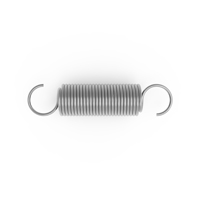
All of Century Spring's stocked extension springs are constant-diameter helical coil springs that feature a variety of hook/loop end types and styles. Every extension spring has an initial tension force that must be overcome before the helical coils visibly separate from adjacent coils. This provides a force that secures the spring for installation, sometimes referred to as the “holding” force. Century Spring extension springs are made with either machine hook or full loop ends unless explicitly noted in the catalogue specification.
Note: If the spring needed for your application cannot be found in our inventory, we can fabricate it for you. Simply request a quote.
Extension Spring Design Information
Spring Sizing
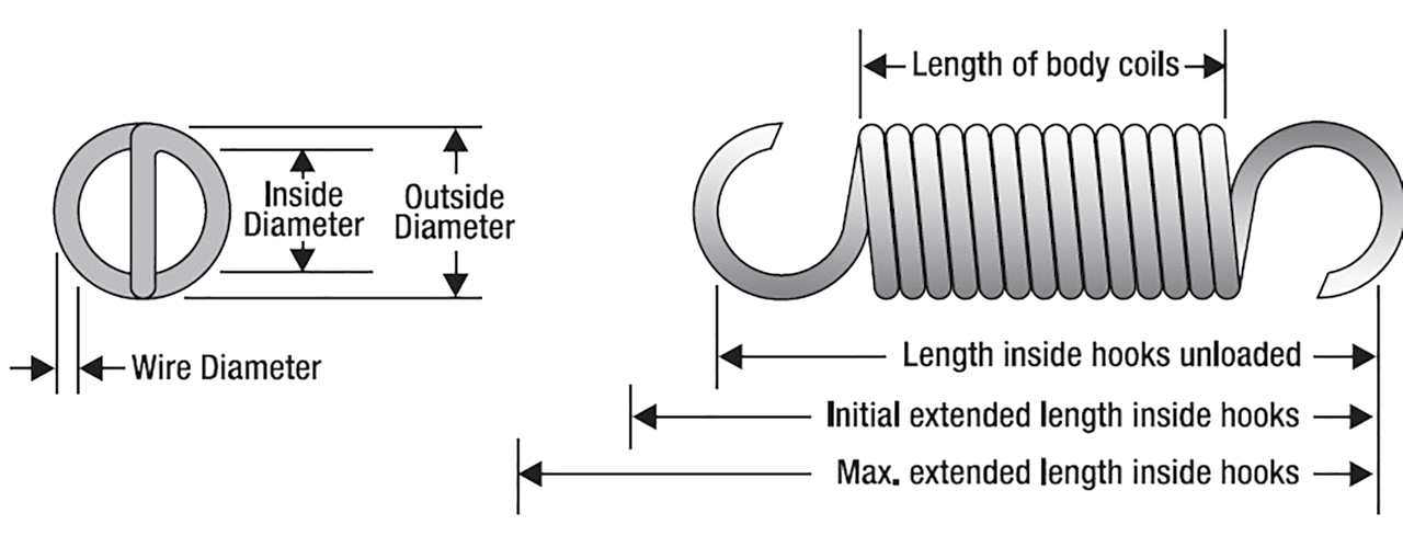
First, determine the approximate Outer Diameter (O.D.) and Length of the body coils of the extension spring you need.
- The Spring Rate is the load (lb) required to stretch the spring a distance of one inch (in). For example, if an extension spring has a spring rate = 40 lb/1 in, it would take 10 lb of force to extend it a distance of 1/4 in, while it would require 80 lb of applied force to extend the spring 2 in. The applied force must overcome the extension spring’s Initial Tension (IT) before the spring extends in length.
- The load needed to stretch a spring a given distance is equal to the initial tension added to the extended distance of the spring multiplied by its spring rate.
Total Force = I.T. + Deflection x Rate
If your spring's O.D. and/or length are not critical design constraints, you should review the Maximum Suggested Load for springs in the general size ranges you require. This spring specification value is the corresponding force at the spring’s Maximum Suggested Deflection specification and includes the spring’s Initial Tension (IT). For clarification, the Maximum Suggested Deflection value represents the additional distance an extension spring will travel beyond its free length. The suggested maximum deflection and loads listed in the governing spring specification are expected to provide an average spring-cycle lifetime of approximately 50,000 cycles. If your application exceeds this value, you should consider taking steps to ensure the spring operates well within these maximum parameters, to allow for longer service lifetimes. You can use an appropriately sized spring scale to determine the spring load at any given spring deflection value.
Calculating Extension Rate and Stress
The basic spring extension rate can be determined using the formula below.
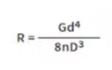
Where:
R = Spring rate (lb./in.)
And:
d = Wire diameter (in.)
D = Mean diameter, defined as: Outer Diameter - d (in.)
G = Modulus e.g., spring steel = 11.5x10⁶, stainless steel = 10x106 (psi.)
n = Number of Active Coils
Finding Spring Stress Rates
The spring’s Minimum Tensile Strength (MTS) is a function of wire diameter and material type. To ensure long fatigue life, the maximum wire stress in the extension spring body coils should remain within 30% to 45% of the MTS value, depending on the selected material. Maintaining operating stress within this range minimizes the risk of fatigue failure during dynamic or high-cycle lifetimes.
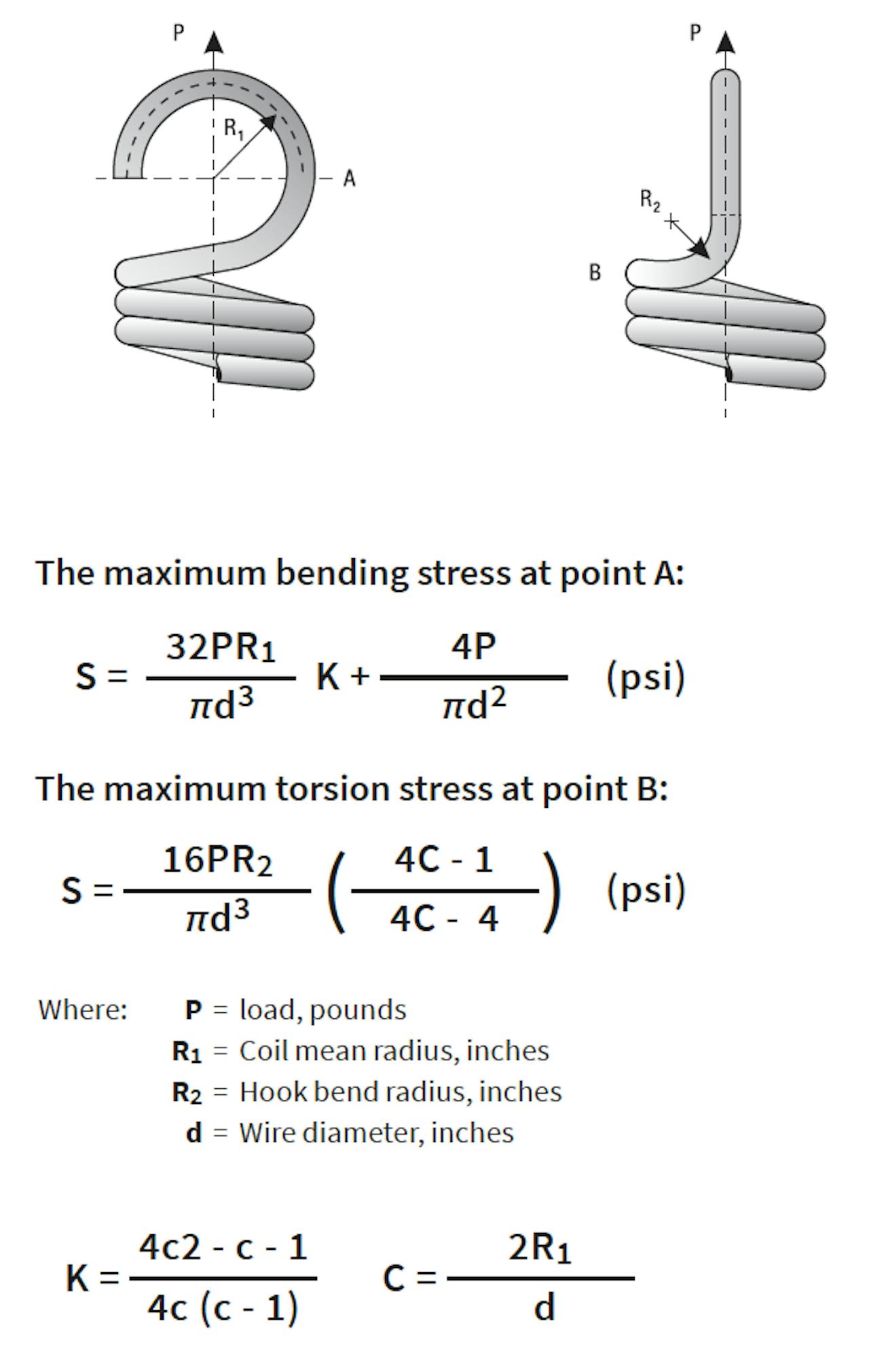
Stresses in the extension spring hooks are typically higher than those in the body of the extension spring at the helical coils because there is a bending stress in addition to the wire-torsion stress, specifically in the transition region between the last body coil and the hook. Therefore, an overstressed extension spring is likely to first fail at the hook end(s). The suggested allowable hook stress under torsion loads is 30-45% of the spring’s MTS, while the allowable stress for bending loads is higher, at 75% of the spring’s MTS.
For detailed MTS guidance by material type—or help designing a custom extension spring that meets specific fatigue life or stress criteria—consult our engineering team.
Furthermore, using the information shown on the right, you can estimate the total stress in a typical extension-spring hook or loop end type.
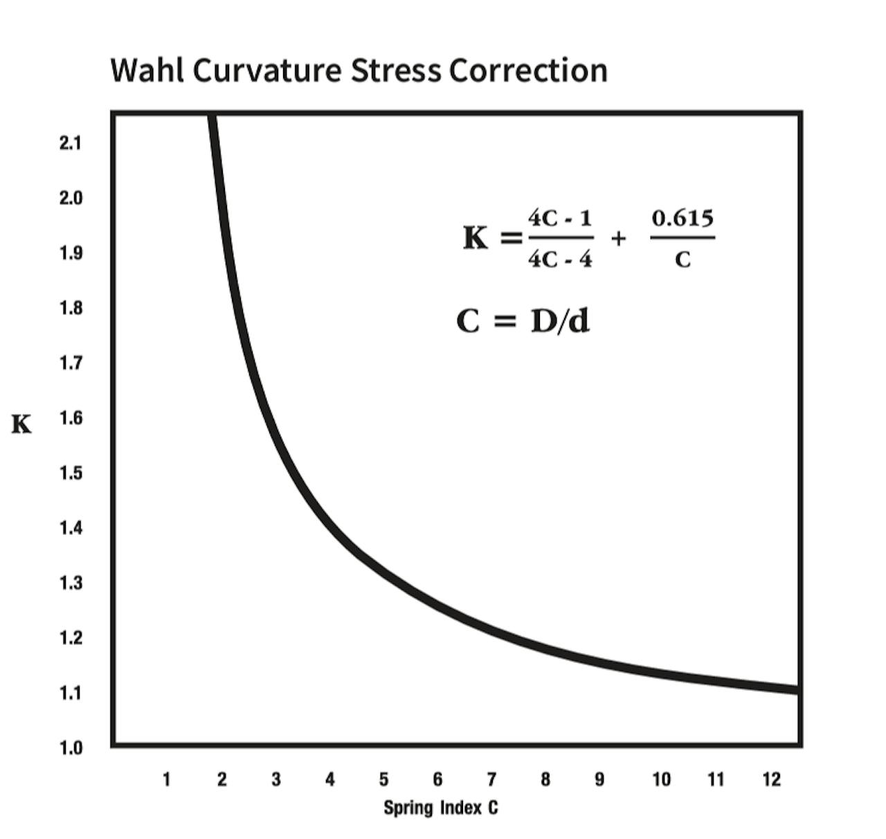
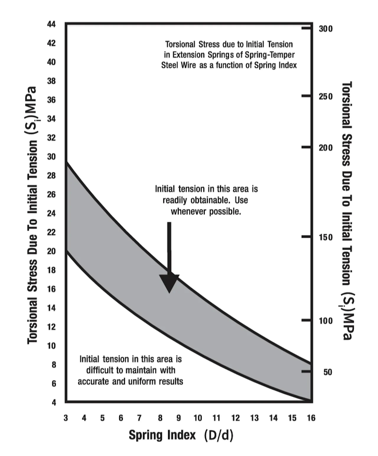
There is an additional consideration that should be accounted for when determining the stress distribution of an extension spring due to the spring’s inherent initial tension. As stated previously, the initial tension stresses the spring body while unloaded. This stress is a function of the ratio between the spring’s Mean Diameter and the Wire Diameter.
Refer to the figures below for a visual representation of stress due to initial tension and a chart showing the Wahl curvature stress correction factor.
Spring Index Charts
Spring Characteristics
- Materials
We always use high-grade spring materials to fabricate all our springs and offer all material certification materials for custom springs and development programs.
For stock spring purchases, we can provide an optional material verification statement for a flat $25. Certifications of conformance for geometric tolerances set by the Spring Manufacturers Institute (SMI) are also available for our stock springs upon request.
Additionally, Spring Steel is an industry term for stock spring materials that encompasses the following: Music wire, Hard-drawn (MB) wire, and Oil-tempered wire.
Stock extension springs are offered in Stainless steel 302 and Stainless steel 316 as specified. - Finish
The finishes available for our torsion springs include:
- Zinc
- Gold Irridite®
- Black Oxide
- Passivated (upon request)
- None (can be plated upon request)
- Tolerances
Tolerances for extension spring rates depend upon the body-diameter to wire-diameter ratio, but are usually about +/- 10% and +/- 5% extension spring’s Outer Diameter. The initial tension is more difficult to control and is listed only as a reference value.
-
 Extension Spring Ends
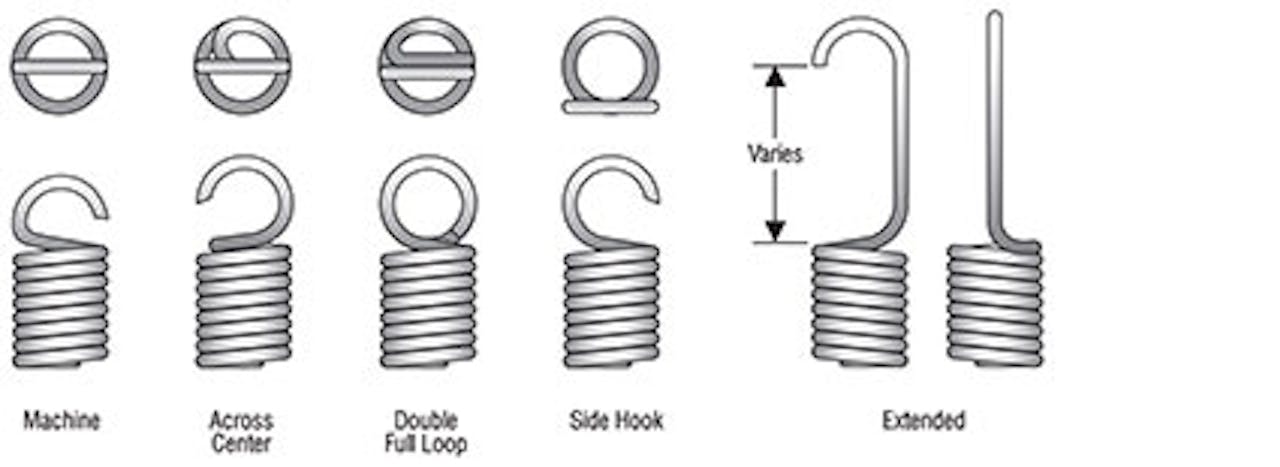
The ends on the extension springs offered in our stock inventory are the common machine-made hook and full-loop configurations. All part numbers in the 80,000 number range are single-full-loop styles. The hooks or loops may have an across-center transition of the last coil before forming the hook or loop (see Figure below). The angle between hook/loop planes is random, meaning the end position is not controlled.
Our stock extension spring end configurations are depicted in the figures to the right.
Contact Us
For further design and engineering resources, visit the Century Spring resource center. You can always contact us directly for specific questions related to our products or services: